High School
Smart Home
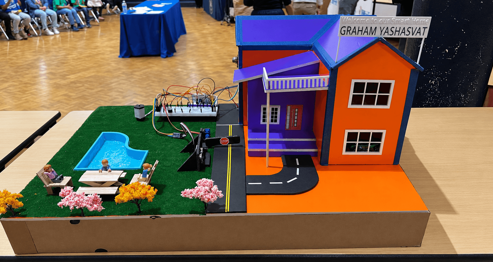
Build a scaled-down smart home model that combines sensors, status indicators, and an automated entry barrier into one coordinated system.
- Level
- Challenger
- Time
- 2 hrs
- Parts
- 6
- Hardware-checked
- Not yet
What this build assumes
- Reading a sensor's input
- Controlling a motor with code
- Designing automated behavior
- Closed-loop sensing and correction
- Differential-drive steering
- Assembling a mobile robot chassis
0 of 5 build milestones complete
What this build is
This capstone build combines multiple sensors, status LEDs, and an automated barrier so several parts of the model can work together as one system.
It introduces the same kind of system integration used in real smart environments, where sensors collect information and automated components respond to changing conditions.
How it works
System architecture
Sensing
The sensors report what is happening in different parts of the model.
Processing
Your code reads those inputs and keeps track of the system's current state.
Control
The LEDs and automated barrier respond based on what the sensors detect.
System
All of the sensing, logic, and outputs run together continuously as one coordinated smart-home system.
Parts
Microcontroller board × 1
Coordinates the sensors, LEDs, and automated barrier as one system.
Ultrasonic distance sensors × multiple
Detect objects or occupancy in different monitored areas of the model.
Micro servo motor × 1
Raises and lowers the automated entry barrier.
Status LEDs × multiple
Provide visible feedback about what the sensors are detecting.
Breadboard × 1
Holds the electronic connections for the sensors, LEDs, and servo.
Jumper wires × a bundle
Connect the sensors, LEDs, and servo to the microcontroller.
Build
- 1
Plan the smart-home system
Decide where each sensor, status indicator, and automated component will be placed before wiring anything.
- 2
Mount the sensors
Position the ultrasonic sensors so they can reliably detect objects in the areas you want the system to monitor.
Sensor placement diagram
Not drawn yet. We only publish a diagram once someone has built this with real parts and checked it — so rather than guess at the connections, we are telling you they are missing. The written wiring notes are accurate.
- 3
Wire the status LEDs
Connect the status LEDs through current-limiting resistors to the microcontroller so the system can provide visible feedback.
Status LED wiring diagram
Not drawn yet. We only publish a diagram once someone has built this with real parts and checked it — so rather than guess at the connections, we are telling you they are missing. The written wiring notes are accurate.
- 4
Attach the automated entry barrier
Connect the barrier arm to the servo horn and mount the servo securely at the entrance.
Entry barrier diagram
Not drawn yet. We only publish a diagram once someone has built this with real parts and checked it — so rather than guess at the connections, we are telling you they are missing. The written wiring notes are accurate.
- 5
Connect the full system
Connect every sensor, LED, and the servo to power, ground, and the correct signal pins on the microcontroller.
Full system wiring diagram
Not drawn yet. We only publish a diagram once someone has built this with real parts and checked it — so rather than guess at the connections, we are telling you they are missing. The written wiring notes are accurate.
- 6
Upload the system code
Connect the microcontroller to your computer and upload the code below.
- 7
Test each subsystem
Test the sensors, LEDs, and barrier separately before running everything together.
- 8
Test the complete smart home
Trigger different sensors and confirm that the system updates its indicators and automated barrier correctly.
Wiring
Smart Home wiring diagram
Not drawn yet. We only publish a diagram once someone has built this with real parts and checked it — so rather than guess at the connections, we are telling you they are missing. The written wiring notes are accurate.
Each ultrasonic sensor connects to power and ground, with trigger and echo connected to digital pins. Each status LED connects through a current-limiting resistor to a digital output. The servo's signal wire connects to an appropriate control pin. Match every connection to the pins defined in your code, and plan your available pins before wiring the full system.
Code
1#include <Servo.h>2 3Servo barrier;4 5const int servoPin = 9;6 7const int trigPins[2] = { 10, 12 };8const int echoPins[2] = { 11, 13 };9 10const int redPins[2] = { 2, 4 };11const int greenPins[2] = { 3, 5 };12 13const int detectionThresholdCm = 10;14 15int openZones = 2;16 17void setup() {18 barrier.attach(servoPin);19 20 for (int i = 0; i < 2; i++) {21 pinMode(trigPins[i], OUTPUT);22 pinMode(echoPins[i], INPUT);23 24 pinMode(redPins[i], OUTPUT);25 pinMode(greenPins[i], OUTPUT);26 }27}28 29void loop() {30 openZones = 0;31 32 for (int i = 0; i < 2; i++) {33 long distanceCm = readDistanceCm(i);34 35 bool detected =36 distanceCm > 0 &&37 distanceCm < detectionThresholdCm;38 39 digitalWrite(40 redPins[i],41 detected ? HIGH : LOW42 );43 44 digitalWrite(45 greenPins[i],46 detected ? LOW : HIGH47 );48 49 if (!detected) {50 openZones++;51 }52 }53 54 if (openZones > 0) {55 barrier.write(90);56 } else {57 barrier.write(0);58 }59 60 delay(50);61}62 63long readDistanceCm(int index) {64 digitalWrite(trigPins[index], LOW);65 delayMicroseconds(2);66 67 digitalWrite(trigPins[index], HIGH);68 delayMicroseconds(10);69 70 digitalWrite(trigPins[index], LOW);71 72 long duration =73 pulseIn(echoPins[index], HIGH, 30000);74 75 if (duration == 0) {76 return -1;77 }78 79 return duration * 0.034 / 2;80}81 - Line 13: detectionThresholdCm controls how close an object must be before the system considers it detected.
- Line 48: The barrier responds to the state created from the sensor readings, connecting sensing, processing, and physical action.
Expected behaviour
- 1Upload the code and test one sensor at a time.
- 2Move an object in front of a sensor and confirm its status LEDs change.
- 3Test the servo separately and confirm the barrier can move through its intended range.
- 4Run the entire system and confirm the sensor readings, status indicators, and barrier work together.
- 5Repeat different combinations of sensor inputs to make sure the system behaves consistently.
Diagnosis
Symptoms and their usual causes. Work down the list — each check rules out a subsystem.
- A status LED shows the wrong state.
- Check that the sensor and its corresponding LED pins use the same array position in the code.
- The barrier does not move.
- Test the servo by itself first and confirm the servoPin in the code matches the physical connection.
- The barrier reacts incorrectly.
- Print the sensor readings to the Serial Monitor and confirm the state logic is interpreting them correctly.
- Sensors interfere with each other.
- Ultrasonic sensors placed close together can interfere with one another. Read them one at a time and add a short delay between measurements if necessary.
- The system works one part at a time but fails when everything runs together.
- Test each subsystem independently, then reconnect them one at a time until you identify which connection or section of code causes the problem.
Open problems
Extensions
Small change
Add a live status display
Display the current state of the smart-home system using additional LEDs or another output device.
Add something
Improve the automated entrance
Add more conditions that determine when the entry barrier should open or remain closed.
Add something
Log system activity
Print a message whenever one of the monitored areas changes state or the automated barrier moves.
Design it yourself
Add another automated subsystem
Design another sensor-controlled feature and integrate it into the existing smart-home logic.
You decide how it works. No steps for this one.
Check your understanding
1. What makes this project a system instead of a collection of separate components?
2. What role does the microcontroller play in the smart-home system?
3. Why should you test each subsystem separately when debugging?
Where this leads
You now know:
- Integrating multiple subsystems into one system
- Reading and comparing multiple sensors
- Tracking state across a program
- Driving a status display from program state
- Debugging a system part by part
- Combining sensor input with motor output
- Using conditional (if/else) logic
That is every project in the library. Go back to any of them and take on the harder changes at the bottom — those are the part nobody walks you through. All projects